I have bought this module for a while, and I recently reorganized the module at hand, and use these few days to implement the functions of this module.Infrared reflection tracking/obstacle avoidance module TCRT5000 uses the characteristics of infrared reflection and has two applicable functions. One is to detect whether an object is approaching. When the module is installed in a car, it can detect whether there is an obstacle in front of it. Another function is to judge whether the car deviates from the drawn route by changing the color of the reflective surface. The following are implementation instructions and results.

The infrared emitting diode of the TCRT5000 tracking sensor module continuously emits infrared rays. When the emitted infrared rays are not reflected back or reflected back but the intensity is not strong enough, the phototransistor is always in the off state. The output terminal is low potential, indicating that the diode is always off; when the detected object appears in the detection range, the infrared rays are reflected back and the intensity is large enough, and the output terminal of the phototransistor is at high potential at this time, indicating the diode The body lamp is lit.
Product specifications:

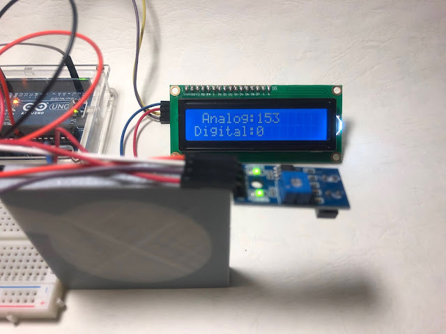
In these two photos, after placing a black anti-slip pad under the sensor, the analog value has changed from 153 to 735, indicating that the black blocks part of the reflected light source, resulting in a decrease in reflection and an increase in the value of the analog received signal.

The following two photos show the proximity of an object. When the module receives a reflection signal, the D0 pin will output 0. When the sensor is increased a little bit, the D0 pin outputs 1, and the analog value is about 540 as the separation. When it is less than 540, it means that an object is detected close. When it is greater than 540, it means that there is no object within the distance range. As a result, when the light is sufficient, the detectable object distance must be within 8 cm.


The infrared emitting diode of the TCRT5000 tracking sensor module continuously emits infrared rays. When the emitted infrared rays are not reflected back or reflected back but the intensity is not strong enough, the phototransistor is always in the off state. The output terminal is low potential, indicating that the diode is always off; when the detected object appears in the detection range, the infrared rays are reflected back and the intensity is large enough, and the output terminal of the phototransistor is at high potential at this time, indicating the diode The body lamp is lit.
Product specifications:
- Using TCRT5000 infrared reflection sensor
- Detection reflection distance: 1mm~25mm applicable
- Working voltage 3.3V-5V
- Output form: digital switch output (0 and 1) and analog output two
- Use wide voltage LM393 comparator
[Material]
- Arduino Uno
- Infrared reflection tracking/obstacle avoidance module TCRT5000
- LCD1602 liquid crystal display
- I2C/interface LCD1602 adapter board PCF8574
- Breadboard x1
- Wire x N
[Wiring diagram]
| Arduino | INFRARED REFLECTION TRACKING/OBSTACLE AVOIDANCE MODULETCRT5000 | LCD1602 Display |
|---|---|---|
| +5V | VCC | VCC |
| GND | GND | GND |
| D2 | DO | - |
| A0 | AO | - |
| SDA | - | SDA |
| SCL | - | SCL |

[Code]
#include <LiquidCrystal_I2C.h>   // include LiquidCrystal_I2C Library
LiquidCrystal_I2C lcd(0x27,16,2);  // Set the LCD address to 0x27, with 16 characters and 2 columns

int DigitalPin = 2;
int AnalogPin = A0;
int ledPin = 13;

void setup()
{
  Serial.begin(115200);
  pinMode(DigitalPin, INPUT);  // set the Digital Pin as input
  pinMode(AnalogPin, INPUT);  // set the analog pin as input
  pinMode(ledPin, OUTPUT);
  lcd.init();                // Initialize lcd
  lcd.backlight();           // Set the back panel to bright
  lcd.clear();
}
void loop()
{
  boolean D_val = digitalRead(DigitalPin); // Read the value of digital Pin
  int A_val = analogRead(AnalogPin);

  if(D_val == HIGH)  {     // When read the value is LOW, turn on the LED of
    digitalWrite(ledPin, LOW);
  }
  else {
    digitalWrite(ledPin, HIGH);
  }
  Serial.print("Analog Data: ");
  Serial.println(A_val);
  lcd.setCursor(0,0);
  lcd.print(" Analog:");
  lcd.print(A_val);
  lcd.print("  ");

  lcd.setCursor(0,1);
  lcd.print("Digital:");
  lcd.print(D_val);
  delay(300);
}
[Result]
The TCRT5000 module has digital and analog two pins, which are connected to the two Arduino interfaces D2 and A0 respectively, and then display the measured sensing value on the LCD1602 to determine when the detected analog value reaches a certain value , The digital signal will change. Using this feature, it can detect (1) the approach of the object, (2) the change of the reflection value of the sensing target due to the change of the color, and judge whether it deviates from the path.In these two photos, after placing a black anti-slip pad under the sensor, the analog value has changed from 153 to 735, indicating that the black blocks part of the reflected light source, resulting in a decrease in reflection and an increase in the value of the analog received signal.


The following two photos show the proximity of an object. When the module receives a reflection signal, the D0 pin will output 0. When the sensor is increased a little bit, the D0 pin outputs 1, and the analog value is about 540 as the separation. When it is less than 540, it means that an object is detected close. When it is greater than 540, it means that there is no object within the distance range. As a result, when the light is sufficient, the detectable object distance must be within 8 cm.


[Reference]
Tags:
Arduino