If you want to use Arduino to measure external voltage, you must use the analog input pin of the Arduino development board. Because the input voltage of Arduino is limited to 5V, the analog input pin of Arduino can only test the maximum voltage of 5V. But what if you want to measure a voltage greater than 5V? At this time, a voltage sensor module is needed. Using this electrical module, you can measure voltages up to 25V.

This module is designed based on the principle of resistance divider, which can reduce the input voltage of the terminal interface by 5 times. The Arduino analog input voltage is up to 5V, so the input voltage of the voltage detection module cannot be greater than 5V×5=25V (if used For 3.3V system, the input voltage cannot be greater than 3.3Vx5=16.5V). Because the AVR chip used by Arduino is 10-bit AD, the analog resolution of this module is 0.00489V (5V/1023), so the minimum input voltage detected by the voltage detection module is 0.00489V×5=0.02445V.
Voltage sensor specifications:
The circuit diagram of the current sensor is as follows:
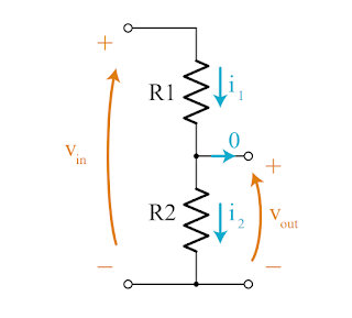
The input current is input from Vin. At this time, the current i1 and i2 are the same. In order to find the voltage value, use Ohm's law (V = i * R) to calculate the voltage value.
This is also the formula for calculating the input voltage vIN = vOUT / (R2/(R1+R2)) in the following formula.


This module is designed based on the principle of resistance divider, which can reduce the input voltage of the terminal interface by 5 times. The Arduino analog input voltage is up to 5V, so the input voltage of the voltage detection module cannot be greater than 5V×5=25V (if used For 3.3V system, the input voltage cannot be greater than 3.3Vx5=16.5V). Because the AVR chip used by Arduino is 10-bit AD, the analog resolution of this module is 0.00489V (5V/1023), so the minimum input voltage detected by the voltage detection module is 0.00489V×5=0.02445V.
Voltage sensor specifications:
- Voltage input range: DC 0 ~ 25V
- Voltage detection range: DC0.02445V ~ 25V
- Voltage analog resolution: 0.00489V
- DC input interface: the positive terminal is connected to VCC, and the negative terminal is connected to GND
The circuit diagram of the current sensor is as follows:

Source:khanacademy.org
The input current is input from Vin. At this time, the current i1 and i2 are the same. In order to find the voltage value, use Ohm's law (V = i * R) to calculate the voltage value.
Vin = i * (R1 + R2)  ie.
i = Vin / (R1 + R2)
To calculate the output voltage, use Ohm’s law to calculate, Vout = i * R2, and substituting the current i in the above formula into the formula.
Vout = (Vin / (R1 + R2)) * R2To know the input voltage Vin, according to the above formula:
Vin = Vout / (R2/(R1+R2))
This is also the formula for calculating the input voltage vIN = vOUT / (R2/(R1+R2)) in the following formula.
[Material]
- Arduino Uno
- Voltage Sensing Module
- LCD1602 liquid crystal display
- I2C/interface LCD1602 adapter board PCF8574
- Breadboard x1
- 9V battery x1
- Wires x N
[Wiring diagram]
| Arduino | Voltage Sensor | LCD1602 |
|---|---|---|
| +5V | VCC | VCC |
| GND | GND | GND |
| A0 | S | - |
| SDA | - | SDA |
| SCL | - | SCL |

[Code]
#include <LiquidCrystal_I2C.h>   // reference LiquidCrystal_I2C Library
LiquidCrystal_I2C lcd(0x27,16,2);  // Set the LCD address to 0x27, with 16 characters and 2 columns

const int voltageSensor = A0;
float vOUT = 0.0;
float vIN = 0.0;
float R1 = 30000.0;
float R2 = 7500.0;
int value = 0;

void setup()
{
  Serial.begin(112500);

  lcd.init();         // initialize lcd
  lcd.backlight();      // Set the back panel to be bright
  lcd.clear();
  lcd.setCursor(0,0);
  lcd.print("Measure Voltage");
}

void loop()
{
  value = analogRead(voltageSensor);
  vOUT = (value * 5.0) / 1024.0;
  vIN = vOUT / (R2/(R1+R2));
  Serial.print("Input = ");
  Serial.print(vIN);
  Serial.println(" V");
  lcd.setCursor(0,1);
  lcd.print("Input = ");
  lcd.print(vIN);
  lcd.print(" V");
  delay(500);
}
[Result]
The 9V voltage measured by the voltage sensor is 9.50V, and the same battery is measured by the electric meter. The result is 9.57V, which is 0.07 different from the data measured by the voltage sensor.
Tags:
Arduino